SVPWM motor control
A project I’m working on calls for a reaction wheel actuated by a small, lightweight motor. By “lightweight” I mean the motor + reaction wheel needs to be less than ~10 grams. Motors typically used in reaction wheels are significantly heavier than this, in part because they include features like optical encoders that help the control algorithm. So I started to investigate whether the small brushless DC (BLDC) motors used on flying drones could be used in such a low-weight, low-speed reaction wheel system.
Controlling these sensorless motors at low speed is tricky. Motor controllers (for example drone ESCs) usually rely on detecting the back EMF from the spinning motor to sense motor position, and perform accurate commutation. However this back EMF is too small to detect at low spin rate. What ESCs typically do is execute an open-loop acceleration phase to get the motor spinning fast enough to sense back EMF, at which point they transition to closed-loop control using back EMF to sense rotor position.
Enter: Space Vector PWM
This project controls BLDC motors in a different way, using a space vector pulse width modulation (SVPWM) control scheme. It demonstrates accurate position control at very low speeds, as well as bidirectional control. See this video for an example of the control available with this technique:
SVPWM is described in several tutorials online, and for convenience we adopt the terminology and notation from one in particular, Application Note AN2154 from STMicroelectronics.
The gist of SVPWM uses the fact that the three phase coils inside the motor are arranged with a 120° separation from one another. Each coil acts like a solenoid generating a magnetic field along its axial direction, with magnitude proportional to the current through that coil. The total magnetic field is the vector sum of all three. The permanent magnets in the rotor have a magnetic axis of their own, and feel a net torque if this axis isn’t aligned with the coil field. What SVPWM does is arrange the coil currents to get a that aligns with the desired rotor angle.
One subtlety is that the three coil currents aren’t independent. Since there is no center tap, by Kirchoff’s current law for the currents entering each of the three coils. In other words you only have two degrees of freedom in controlling the coil currents, since . Still, two degrees of freedom are enough to specify any that lies in a plane. A bit of trigonometry works out the necessary currents.
A second subtlety is that, practically speaking, you control the time-averaged current through each coil using pulse width modulation of the driving voltage. A typical small motor might have of winding resistance, and applying a 7.7 volt drive across it will rapidly give rise to a current of amps, and Watts of heat! One solution is to turn on the drive for a brief period of time, then turn it off, then back on, and so on. When the drive is applied, inductance in the coil prevents the current from spiking immediately: Instead the current increases at a rate , where is the applied voltage and is the coil inductance. For small motors like this, is on the order of amps/sec and if we switch off the drive within a few microseconds we can prevent an overcurrent.
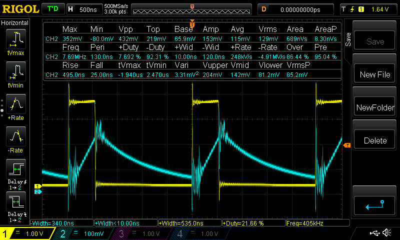
We can see current chopping in action in the following scope trace. Yellow is the applied 400 kHz driving signal to a coil, and blue is proportional to the measured coil current. When the drive is applied current increases linearly due to the nonzero coil inductance, and when the drive shuts off it decays back toward zero.
A final subtlety is that SVPWM is a precise method of control only to the extent that the motor behaves in an idealized way. In this case the main departures from ideal behavior are:
- Non-sinusoidal back EMF. In a textbook motor there is a sinusoidal relationship between the rotor’s magnetic flux through the motor coils (“linkage flux”), and turning angle. (Or alternatively, the motor generates a precisely sinusoidal back-EMF when turned at constant speed.) Due to the way the coils are wound in real motors, however, most BLDC motors give a more trapezoidal back EMF profile. Some motors are wound specifically to give a sinusoidal back-EMF: so-called “sinusoidally-wound” motors, or PMSMs (permanent magnet synchronous motors).
- Nonzero reluctance torque. Reluctance torque is caused by the permanent magnets in the rotor interacting with iron in the stator, in the absence of stator current. It’s the bumpiness you feel when you turn the motor with your fingers when it’s turned off. If you look closely at the video you can see some small-scale jerkiness in the movement of the rotor; this is reluctance torque.
Long story short, the SVPWM technique isn’t a precise method of control for BLDC motors, but it does reasonably well as can be seen in the video.
The code and hardware
This code is available on Github. It runs as-is on a NUCLEO-F446RE development board with mounted X-NUCLEO-IHM17M1 motor driver. Other hardware configurations may likely require some adaptation. A complete list of hardware needed:
- NUCLEO-F446RE.
- X-NUCLEO-IHM17M1.
- Power source for the motor driver: between 3 and 10 volts, and able to supply a few amps peak. You could use a power supply, or a 1S or 2S LiPo battery.
- A drone motor. I’ve tested with small motors in the 4000-8000 KV range, but others
should work. NOTE: be sure your motor can handle 1.3 amps through its coils
without generating too much heat. For drone motors this won’t be an issue, but
for motors with more turns and higher winding resistance (e.g., gimbal motors)
this could be a problem. You can adjust the max. driving current in this line:
start_tim3_pwm(&clocks, 0.15)where the 0.15 is the current limit in amps (peak, not rms). - A mini USB cable (not micro USB!) to connect your computer to the NUCLEO’s onboard ST-LINK debugger.